
Embraco NT2180GK Refrigeration Compressor
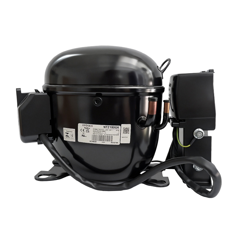
Embraco NT2180GK Refrigeration Compressor: R-404A LBP Technical Data and Selection Guide
The Embraco NT2180GK is a single-phase, 220-240 V 50 Hz hermetic reciprocating compressor rated for low back pressure (LBP) R-404A duty. It displaces 20.44 cm3, and the manufacturer data sheets that document it publish 508 W to 530 W of cooling capacity at the EN 12900 rated point of -35 C evaporating and 40 C condensing, at a coefficient of performance of 1.00 to 1.05 W/W.
What Is the Embraco NT2180GK?
The NT2180GK is a fixed-speed hermetic reciprocating compressor in the Embraco Aspera NT family, built in Slovakia and sold for commercial low-temperature refrigeration. It runs on R-404A at 220-240 V and 50 Hz, is declared with high starting torque (HST), accepts either a capillary tube or an expansion valve, and spans an evaporating temperature range of -40 C to -10 C. Its published commercial designation is 1 hp. Inside the supplier's Embraco Aspera compressor range it sits in the middle of the low back pressure ladder, one displacement step below NT2192GK.
The model suits systems that need a medium-capacity, fan-cooled compressor for frozen and chilled product: reach-in freezers and refrigerated cabinets, fast freezers, ice machines, beverage coolers, and similar low back pressure equipment. The manufacturer's own application tables place it in the R-404A 50 Hz column for reach-in freezer and refrigerator cabinets of up to 350 litres, and in the 60 Hz fast freezer table at the 15 litre size.
Everything in this guide is drawn from manufacturer-issued documents, and one fact about those documents governs the whole page. Four separate technical data sheets for this single model are in circulation, and they disagree. They print the rated capacity as 530 W, 529 W, 523 W and 508 W. They print three different engineering codes. They print three different motor types, CSR, CSCR and CSIR. Two of them describe a copper suction connector 9.6 mm across; one describes a steel Rotolock connector 12.7 mm across. None of these differences is a transcription slip on the part of a distributor, because each sheet carries the manufacturer's own document engine footer. Understanding why the sheets diverge, and which figure to quote in which context, is the single most important thing a buyer can take from this page.
Key facts at a glance
| Item | Value | Basis |
|---|---|---|
| Model | NT2180GK | All four manufacturer data sheets, designation field |
| Compressor type | Hermetic reciprocating | Manufacturer sheet, general data |
| Technology | ON/OFF, fixed speed | Manufacturer sheet, general data |
| Refrigerant | R-404A | Manufacturer sheet, refrigerant field; the catalogue nomenclature block decodes GK as R-404A |
| Nominal voltage and frequency | 220-240 V, 50 Hz, single phase | Manufacturer sheet, electrical data section 1 |
| Application envelope | LBP, low back pressure R-404A | Manufacturer sheet, application section 4 |
| Evaporating temperature range | -40 C to -10 C | Manufacturer sheet, application section 4.1 |
| Displacement | 20.44 cm3 | All four manufacturer sheets, mechanical data |
| Bore | 36.990 mm | Manufacturer sheet, mechanical data section 2.1 |
| Stroke | 19.03 mm | Manufacturer sheet, mechanical data section 2.2 |
| Commercial designation | 1 hp | Manufacturer sheet, mechanical data section 1 |
| Motor type | Not agreed across sheets: CSR, CSCR or CSIR | Cross-sheet comparison of the four data sheets |
| Starting torque class | HST, high starting torque | All four manufacturer sheets |
| Cooling capacity, EN 12900 rated point | 508 W to 530 W, depending on the sheet | Manufacturer sheets, rated point at -35 C evaporating and 40 C condensing |
| Efficiency, EN 12900 rated point | 1.00 to 1.05 W/W | Manufacturer sheets, rated point at the same conditions |
| Oil charge and type | 450 ml, ester ISO22 | All four manufacturer sheets, mechanical data |
| Maximum recommended refrigerant charge | 800 g | All four manufacturer sheets, performance header |
| Weight with oil charge | 17.4 kg, with one sheet printing 18 kg | Manufacturer sheets, mechanical data |
| Maximum condensing pressure, operating | 24.71 bar gauge | Manufacturer sheet, general data; a second sheet prints 24.7 bar |
| Maximum condensing pressure, peak | 27.71 bar gauge | Manufacturer sheet, general data; a second sheet prints 27.7 bar |
| Maximum winding temperature | 130 C | Manufacturer sheet, application section 10 |
| Fan air flow | 520 m3/h | Manufacturer sheet, general data |
| Locked rotor amperage at 50 Hz | 35.0 A, measured to UL 984 | Manufacturer sheet, electrical section 8 |
| Approval boards certification | IMQ | Manufacturer sheet, electrical section 11 |
| Origin plant | Slovakia | All four manufacturer sheets, plant field |
The capacity row deserves a note before it is read as a spread of opinion. All four sheets rate the compressor on the same standard, EN 12900, at the same evaporating and condensing temperatures, and the same 0 K liquid subcooling with 20 C return gas. The 530 W, 529 W, 523 W and 508 W figures are therefore four answers to one identical question, not four answers to four different questions. That is what makes the disagreement worth reporting rather than explaining away.
How do you read the NT2180GK model code?
Embraco model strings are positional. The letters and digits encode family, capacity class, refrigerant envelope, motor variant and revision. The table below decodes each block of NT2180GK against what the manufacturer documents actually confirm, and marks the blocks the documents do not explain.
| Block | Value in NT2180GK | What the manufacturer documents confirm | Status |
|---|---|---|---|
| Family letters | NT | Used throughout the low back pressure R-404A ladder in the 220-240 V 50 Hz catalogue section, alongside NEU, NEK and NJ series | Confirmed as a within-family series marker |
| Capacity ordinal | 2180 | Not a literal displacement. The catalogue prints 20.44 cm3 beside it, so the block is an ordinal, not centimetres cubed | Confirmed as non-literal |
| Refrigerant code | GK | The catalogue nomenclature page lists the code GK against R-404A in its refrigerant-code block | Confirmed by the catalogue nomenclature page |
| Motor designation | Not present in the string | The four sheets print CSR, CSCR and CSIR for this one model string | Confirmed as absent from the string |
| Torque designation | HST | High starting torque, stated on all four sheets and in the catalogue torque column | Confirmed by the application section |
| Trailing V | Absent from NT2180GK, present on NT2180GKV | The catalogue prints NT2180GKV in both the 220-240 V 50 Hz and the 208-230 V 60 Hz R-404A LBP sections | Undefined in the nomenclature page |
The digits 2180 deserve the same warning that applies across this family. Reading them as 21.80 cm3 would overstate the compressor by about seven percent. The catalogue prints 20.44 cm3 beside this model, all four manufacturer sheets print 20.44 cm3 in their mechanical data, and the bore and stroke on the fullest sheet, 36.990 mm and 19.03 mm, give a swept volume consistent with two cylinders at that displacement. Displacement must always be taken from the data table, never from the model string.
The sibling ladder carries a second warning. Displacement does not rise in step with the ordinal. NJ2212GK displaces 34.38 cm3, yet its ordinal is only 32 higher than the 2180 in NT2180GK, while the intervening NT2210GK and NT2212GK models displace 26.21 cm3 and 27.80 cm3. A buyer who ranks these models by model number rather than by the displacement column will misjudge the step sizes, and the error compounds because the catalogue's own capacity column for this ladder is not monotonic either.
What Are the Technical Specifications of the NT2180GK?
Application and operating limits
The manufacturer sheets list the working limits that govern system design. The maximum condensing pressures are stated as gauge pressures, and the winding temperature limit is the value used when configuring motor protection.
| Limit | Value | Unit | Basis |
|---|---|---|---|
| Evaporating temperature range | -40 to -10 | C | Manufacturer sheet, application section 4.1 |
| Maximum condensing pressure, operating (gauge) | 24.71 | bar | Manufacturer sheet, general data |
| Maximum condensing pressure, peak (gauge) | 27.71 | bar | Manufacturer sheet, general data |
| Maximum winding temperature | 130 | C | Manufacturer sheet, application section 10 |
| Nitrogen holding charge | 0.2 to 0.3 | bar | Manufacturer sheet, mechanical data |
| Expansion device | Capillary tube or expansion valve | - | Manufacturer sheet, application section 7 |
| Compressor cooling | Fan, uncontrolled, 220 V | - | Manufacturer sheet, general data |
| Fan air flow | 520 | m3/h | Manufacturer sheet, general data |
| Free internal volume | 3.3 | L | Manufacturer sheet, mechanical data |
| Height | 234 | mm | Manufacturer sheet, external characteristics |
| Base plate | Universal | - | Manufacturer sheet, external characteristics |
| Tray holder | No | - | Manufacturer sheet, external characteristics |
One caution belongs with this table. The widest sheet also carries an operating voltage range block that sets out separate LBP voltage windows for 32 C and 43 C ambient, and every cell of that block is printed as a dash in the retrieved copy. The ambient-derived voltage windows therefore cannot be quoted from this model's sheets at all, and this guide does not attempt to infer them from another model.
The free internal volume and the fan air flow are worth flagging as design inputs rather than trivia. A service technician sizing a replacement will need the 3.3 litre internal volume to decide how much refrigerant the circuit can hold, and the 800 g maximum recommended charge that all four sheets print is the ceiling that decision has to respect.
Mechanical data
| Parameter | Value | Unit | Basis |
|---|---|---|---|
| Commercial designation | 1 | hp | Manufacturer sheet, mechanical data section 1 |
| Displacement | 20.44 | cm3 | All four manufacturer sheets, mechanical data |
| Bore | 36.990 | mm | Manufacturer sheet, mechanical data section 2.1 |
| Stroke | 19.03 | mm | Manufacturer sheet, mechanical data section 2.2 |
| Cylinder count | Not printed | - | No sheet states it |
| Lubricant charge | 450 | ml | All four manufacturer sheets, mechanical data |
| Lubricant type and viscosity | Ester, ISO22 | - | All four manufacturer sheets, mechanical data |
| Weight with oil charge | 17.4, with one sheet printing 18 | kg | Manufacturer sheets, mechanical data |
| Pressurization | Dry air charge | - | Manufacturer sheet, mechanical data |
The 17.4 kg and 18 kg figures are printed by different manufacturer sheets for the same compressor, and the difference is larger than rounding can explain at this mass. Both are reported here because neither sheet is more recent in a way that settles the question. The sheet that prints 18 kg was generated in December 2024, and the two sheets that print 17.4 kg were generated in February 2022 and September 2024. The mass to use for shipping calculations should be confirmed against the current sheet supplied with the order.
The lubricant specification is uniform across all four sheets and is one of the few parameters where the family is consistent. Ester oil at ISO22 viscosity in a 450 ml charge is the specified fill, and that specification matters for R-404A systems because ester lubricants are hygroscopic and the circuit must be kept dry during installation.
Electrical data
| Parameter | Value | Unit | Basis |
|---|---|---|---|
| Nominal voltage, frequency, phases | 220-240 V, 50 Hz, 1 phase | - | Manufacturer sheet, electrical data section 1 |
| Motor type | CSR on one sheet, CSCR on two sheets, CSIR on one sheet | - | Cross-sheet comparison of the four data sheets |
| Starting torque | HST | - | All four manufacturer sheets |
| Starting device | Voltage relay 3ARR3B6AC3 on one sheet, RVA2L3C-112 on another, relay MTRPH-59 on a third | - | Manufacturer sheets, electrical components section |
| Start capacitor | 130-156 uF at 330 V on three sheets, 88-108 uF at 330 V on one sheet | uF | Manufacturer sheets, electrical components section |
| Run capacitor | 17.5 uF at 440 V on one sheet, 15.0 uF at 440 V on another, not fitted on the other two | uF | Manufacturer sheets, electrical components section |
| External motor protection | T0659/G9, T0743/G9 or T0748/G9, depending on the sheet | - | Manufacturer sheets, electrical components section |
| Start winding resistance at 25 C | 8.56, 8.56, 9.24 or 8.4, depending on the sheet | ohm | Manufacturer sheets, electrical data |
| Run winding resistance at 25 C | 1.82, 1.82, 2.35 or 1.9, depending on the sheet | ohm | Manufacturer sheets, electrical data |
| Locked rotor amperage at 50 Hz | 35.0, measured to UL 984 | A | Manufacturer sheet, electrical section 8 |
| Full load amperage at 50 Hz | Not printed | A | Manufacturer sheet, electrical sections 9 and 10 |
| Approval boards certification | IMQ | - | Manufacturer sheet, electrical section 11 |
The winding resistance rows are the clearest illustration of how far the sheets diverge, because winding resistance is a physical property of the motor that a technician will measure directly. The two sheets that print 8.56 ohm and 1.82 ohm agree with each other to two decimal places. The third sheet prints 9.24 ohm and 2.35 ohm, which is 8 percent higher on the start winding and 29 percent higher on the run winding. The fourth prints 8.4 ohm and 1.9 ohm, bracketed between the two positions. A technician who measures 8.6 ohm on a start winding and compares it against the 9.24 ohm figure would conclude the winding is out of tolerance, when in fact it matches a different manufacturer sheet for the same part number.
The motor type disagreement is more consequential than the resistance spread, because it decides whether a run capacitor is required. A CSR motor is capacitor start, induction run, and needs only a start capacitor. A CSCR motor is capacitor start, capacitor run, and needs both a start capacitor and a run capacitor in the circuit permanently. A CSIR motor is capacitor start, induction run with a different winding arrangement, and again needs only the start capacitor. Since the sheets disagree on this point, the run capacitor question cannot be settled from documents alone. The reliable procedure is to read the nameplate and the terminal box on the specific unit, because a CSCR unit operated without its run capacitor will draw excessive current and a CSR unit fitted with an unnecessary run capacitor will misbehave under light load.
The locked rotor amperage figure of 35.0 A is the value to use for circuit protection sizing, and it carries a footnote worth reading. It is measured according to UL 984, which is the standard the sheet names in the unit column. Any other locked rotor figure circulating for this model should be checked for its measurement basis before it is used to size a breaker.
External connections and installation envelope
| Feature | Value | Unit | Basis |
|---|---|---|---|
| Suction connector, internal diameter | 9.6, and 12.7 on the sheet that prints a Rotolock joint | mm | Manufacturer sheets, external characteristics |
| Suction connector, shape and material | Vertical, copper; steel on the Rotolock sheet | - | Manufacturer sheets, external characteristics |
| Discharge connector, internal diameter | 6.42 | mm | All four manufacturer sheets, external characteristics |
| Discharge connector, shape and material | Vertical, copper | - | All four manufacturer sheets, external characteristics |
| Process connector, internal diameter | 6.42 | mm | All four manufacturer sheets, external characteristics |
| Process connector, shape and material | Vertical, copper | - | All four manufacturer sheets, external characteristics |
| Suction connector thread, Rotolock sheet only | 1 inch -14UNS-2A external thread | - | Manufacturer sheet, external characteristics |
The suction connector disagreement is the one that will stop an installer, because it changes the pipework rather than a number in a table. Three of the four sheets print a 9.6 mm copper connector in a vertical orientation. The fourth prints a 12.7 mm steel connector with a Rotolock threaded joint, 1 inch by 14 UNS 2A. A copper fitting for 9.6 mm tubing will not join to a 12.7 mm threaded steel port, and no adapter is described on any sheet. Before ordering, the connector type should be confirmed against the unit's nameplate photograph or the current sheet, because the two configurations are both documented as belonging to the model string NT2180GK.
The base plate and tray holder entries are simpler. All four sheets declare a universal base plate, printed as Universal on the widest sheet and as UNI on the other two that print it at all, and every sheet declares no tray holder. Base plates and tray holders are the mounting interface, so a buyer who intends to drop this compressor into an existing tray needs to confirm that the universal plate pattern matches the tray rather than assuming the tray holder is supplied.
Why Do the Manufacturer Data Sheets for the NT2180GK Disagree?
The four sheets in circulation
Four technical data sheets for the NT2180GK were retrieved and read in full for this guide. Each one carries a document engine footer identifying the manufacturer's own documentation system, and each one is hosted by a different distributor or service company rather than by the manufacturer, because the manufacturer does not publish a self-hosted model-level data sheet URL for this model. The table below records what each sheet is and when it was generated.
| Sheet | Host | Document engine footer | Engineering code printed |
|---|---|---|---|
| Sheet A | Resluk | Not printed on the retrieved copy | 923HA04 |
| Sheet B | Hutes Klima Technika | Tue, Sep 24, 2024 | 923HA09 |
| Sheet C | Karatas Sogutma | Tue, Dec 10, 2024 | 922HA04 |
| Sheet D | E-Holod | Sat, Feb 26, 2022 | 923HA04 |
The engineering code is the manufacturer's internal identifier for the build configuration, and it is the first place the sheets part company. Sheet A and Sheet D agree on 923HA04. Sheet B prints 923HA09, differing only in the final digit. Sheet C prints 922HA04, differing in the third digit. Because Sheet C is also the sheet that prints the 18 kg weight and the 88-108 uF start capacitor, the code difference appears to track a genuine build difference rather than a typing error, but the manufacturer publishes no decoder for these codes, so the mapping from code to configuration cannot be established from the documents available.
Sheet A is the fullest of the four. It is the only sheet that publishes bore and stroke, the only one that publishes locked rotor amperage, the only one that publishes the approval board, and the only one that carries three complete performance curves at 35 C, 45 C and 55 C condensing with gas flow rate printed at every point. Where the sheets conflict, the guide reports both positions, and where only one sheet carries a parameter, that sheet is named.
The rated point spread
All four sheets are rated on EN 12900, and three of them state the standard explicitly in a performance header. The rated point is -35 C evaporating and 40 C condensing, with 0 K liquid subcooling and 20 C return gas. The table below sets the four answers side by side.
| Parameter at the EN 12900 rated point | Sheet A | Sheet B | Sheet C | Sheet D |
|---|---|---|---|---|
| Cooling capacity | 530 W | 529 W | 523 W | 508 W |
| Power consumption | 507 W | 506 W | 498 W | 509 W |
| Current | 2.42 A | 2.4 A | 2.66 A | Not printed |
| Gas flow rate | 14.35 kg/h | 14.33 kg/h | 14.17 kg/h | 13.61 kg/h |
| Efficiency | 1.05 W/W | 1.05 W/W | 1.05 W/W | 1.00 W/W |
| Tolerance declared | plus or minus 5 percent on capacity | Not printed | Not printed | Not printed |
Read as a set, the four capacity figures span 22 W, which is 4.3 percent of the largest. The declared tolerance on Sheet A is plus or minus 5 percent on capacity, plus or minus 5 percent on power, current and gas flow, and plus or minus 7 percent on efficiency. That tolerance band is wide enough to contain the entire spread between the four sheets. In other words, the four sheets are not contradicting each other about the machine's performance; they are reporting four different measurement samples of a machine whose performance is specified with a 5 percent band, and they happen to fall at different points inside it.
The efficiency column is the exception that proves the rule. Three sheets print 1.05 W/W and one prints 1.00 W/W, and because efficiency is a ratio, it is far less sensitive to the sample than the absolute capacity is. The 1.00 W/W figure on Sheet D comes with a 509 W power draw against a 508 W capacity, so the ratio is arithmetically consistent with its own inputs. Sheet D is also the oldest sheet of the four, generated in February 2022, and its motor type is the outlier CSIR designation. The most economical reading of the evidence is that Sheet D documents an earlier build configuration and that the 1.00 W/W efficiency belongs to that configuration rather than to the current one.
What this means for a quotation
Two practical rules follow from the spread. First, when a quotation states a cooling capacity for the NT2180GK, it must also state the rating basis and the evaporating and condensing temperatures. A bare capacity number for this model is not actionable, because the same machine is documented at 530 W on one sheet and 508 W on another at the same nominal conditions, and neither of those is the figure a real system will see at its own operating point. Second, when comparing quotations from two suppliers, the tolerance band should be applied before any conclusion is drawn. A supplier quoting 523 W is not offering a weaker compressor than a supplier quoting 530 W; both are inside the 5 percent declared tolerance, and the difference will be dominated by the system's pipework and charge long before the compressor's sample-to-sample variation matters.
The third rule concerns service work rather than purchasing. Because the sheets disagree on motor type and on winding resistance, a technician cannot use any single retrieved sheet as the sole reference for a repair. The correct procedure is to identify the build from the unit in hand, then select the sheet whose engineering code and starting device match that build. The two figures to reconcile first are the motor type and the suction connector type, because those two decide whether a run capacitor is needed and whether the pipework will fit.
What Cooling Capacity Does the NT2180GK Produce?
The rated point is a single number. The performance curves are what actually describe the compressor, because they show how the capacity moves as the evaporating and condensing temperatures change around it. Sheet A is the only one of the four manufacturer documents that publishes three complete curve sets with gas flow and current at every point, so its data is reproduced below, with cross-sheet capacity comparisons added where the sheets can be checked against each other, and with a link to the official Embraco catalogue PDF for readers who need the full family data.
All three curve sets are generated to EN 12900 polynomial equations at 220 V and 50 Hz, with fan cooling, 0 K liquid subcooling and 20 C return gas.
Condensing at 35 C
| Evaporating temperature | Cooling capacity | Power consumption | Current | Gas flow rate | Efficiency |
|---|---|---|---|---|---|
| -40 C | 444 W | 438 W | 2.14 A | 11.30 kg/h | 1.01 W/W |
| -35 C | 584 W | 501 W | 2.39 A | 14.90 kg/h | 1.17 W/W |
| -30 C | 763 W | 562 W | 2.65 A | 19.56 kg/h | 1.37 W/W |
| -25 C | 984 W | 622 W | 2.92 A | 25.35 kg/h | 1.58 W/W |
| -20 C | 1248 W | 685 W | 3.20 A | 32.35 kg/h | 1.82 W/W |
| -15 C | 1555 W | 753 W | 3.49 A | 40.64 kg/h | 2.06 W/W |
| -10 C | 1907 W | 827 W | 3.79 A | 50.27 kg/h | 2.31 W/W |
A 35 C condensing temperature is a cool-climate or well-ventilated installation. At the warm end of the published range, -10 C evaporating, the compressor delivers 1907 W of cooling for 827 W of electrical input, an efficiency of 2.31 W/W. At the cold end, -40 C evaporating, it delivers 444 W for 438 W of input, an efficiency of 1.01 W/W. The efficiency roughly doubles across the range, which is the normal behaviour of any reciprocating compressor and the reason a system's running cost is far more sensitive to its evaporating temperature than to its compressor selection.
Condensing at 45 C
| Evaporating temperature | Cooling capacity | Power consumption | Current | Gas flow rate | Efficiency |
|---|---|---|---|---|---|
| -40 C | 332 W | 429 W | 2.10 A | 9.75 kg/h | 0.78 W/W |
| -35 C | 468 W | 510 W | 2.42 A | 13.53 kg/h | 0.92 W/W |
| -30 C | 625 W | 587 W | 2.75 A | 18.20 kg/h | 1.06 W/W |
| -25 C | 814 W | 664 W | 3.10 A | 23.83 kg/h | 1.22 W/W |
| -20 C | 1034 W | 743 W | 3.45 A | 30.50 kg/h | 1.39 W/W |
| -15 C | 1286 W | 825 W | 3.81 A | 38.27 kg/h | 1.56 W/W |
| -10 C | 1573 W | 913 W | 4.18 A | 47.22 kg/h | 1.73 W/W |
The 10 K rise in condensing temperature costs about a quarter of the capacity at every evaporating temperature. At -25 C evaporating, the compressor moves from 984 W at 35 C condensing to 814 W at 45 C condensing, a loss of 17 percent, while the power draw rises from 622 W to 664 W. This is the single most useful table on the page for a system designer working in a warm climate, because a condenser sized for a 35 C day will not hold its evaporating temperature on a 45 C day.
The table below compares all four manufacturer sheets at this condensing level, and the pattern is more informative than the rated-point table was.
| Evaporating temperature | Sheet A | Sheet B | Sheet C | Sheet D |
|---|---|---|---|---|
| -35 C | 468 W | 473 W | 464 W | 436 W |
| -30 C | 625 W | 629 W | 624 W | 592 W |
| -25 C | 814 W | 818 W | 816 W | 772 W |
| -20 C | 1034 W | 1038 W | 1039 W | 976 W |
| -15 C | 1286 W | 1289 W | 1297 W | 1202 W |
| -10 C | 1573 W | 1572 W | 1588 W | 1450 W |
Sheets A, B and C agree with each other to within 1.6 percent at every point in the range, despite the fact that they carry three different engineering codes and are hosted by three different companies. Sheet D is systematically lower, by 6 to 9 percent, at every point. That is not noise. It is the signature of two different build configurations, and it lines up with the other evidence about Sheet D: it is the oldest document of the four, it is the only one that prints a CSIR motor, and it is the only one whose rated point is below 520 W.
Condensing at 55 C
| Evaporating temperature | Cooling capacity | Power consumption | Current | Gas flow rate | Efficiency |
|---|---|---|---|---|---|
| -40 C | Not printed | Not printed | Not printed | Not printed | Not printed |
| -35 C | 338 W | 523 W | 2.52 A | 11.98 kg/h | 0.66 W/W |
| -30 C | 483 W | 614 W | 2.90 A | 16.55 kg/h | 0.78 W/W |
| -25 C | 640 W | 702 W | 3.28 A | 21.91 kg/h | 0.91 W/W |
| -20 C | 814 W | 789 W | 3.68 A | 28.14 kg/h | 1.03 W/W |
| -15 C | 1007 W | 879 W | 4.08 A | 35.29 kg/h | 1.15 W/W |
| -10 C | 1224 W | 974 W | 4.50 A | 43.45 kg/h | 1.25 W/W |
Sheet A prints a dash at -40 C evaporating on this curve set rather than a figure, and the dash is meaningful. It signals that -40 C evaporating combined with 55 C condensing falls outside the compressor's approved envelope, which is a compression-ratio limit rather than a capacity limit. The same dash appears on Sheet D for the whole of its -40 C row at 55 C condensing.
This is the curve set that matters for tropical installations and for equipment sited next to a heat source. At -25 C evaporating and 55 C condensing the compressor delivers 640 W for 702 W of input, an efficiency of 0.91 W/W, which means the electrical input exceeds the useful cooling delivered. A system designed to run continuously at this point will consume more than a kilowatt of electricity for every kilowatt of refrigeration, and that ratio is the strongest argument for improving the condenser airflow or relocating the unit rather than for changing the compressor.
How Does the NT2180GK Perform Across Its Envelope?
The arithmetic check
The published data can be tested against itself, and it holds up. Efficiency is a ratio of capacity to power consumption, so every row of every curve table can be recomputed from the two neighbouring columns. All four sheets pass this audit without exception.
| Curve set checked | Points tested | Points passing the ratio within rounding | Largest deviation |
|---|---|---|---|
| Sheet A, 35 C condensing | 7 | 7 | Under 0.01 W/W |
| Sheet A, 45 C condensing | 7 | 7 | Under 0.01 W/W |
| Sheet A, 55 C condensing | 6 | 6 | Under 0.01 W/W |
| Sheet B, 35 C, 45 C and 55 C | 18 | 18 | Under 0.01 W/W |
| Sheet D, 35 C, 45 C and 55 C | 18 | 18 | Under 0.02 W/W |
The second check is more revealing. The EN 12900 rated point sits at 40 C condensing, exactly halfway between the 35 C and the 45 C curve sets. If the rating is internally consistent, the rated capacity should be close to the midpoint of the two curves at -35 C evaporating. It is, on all four sheets.
| Sheet | Capacity at -35 C on the 35 C curve | Capacity at -35 C on the 45 C curve | Midpoint | Rated point published | Deviation |
|---|---|---|---|---|---|
| Sheet A | 584 W | 468 W | 526 W | 530 W | 0.8 percent |
| Sheet B | 579 W | 473 W | 526 W | 529 W | 0.6 percent |
| Sheet C | 576 W | 464 W | 520 W | 523 W | 0.6 percent |
| Sheet D | 556 W | 436 W | 496 W | 508 W | 2.4 percent |
This result is worth stating plainly, because it changes how the disagreement between the sheets should be read. Every one of the four sheets is internally consistent: its own rated point, its own curves and its own efficiencies all agree with each other. The sheets contradict each other, not themselves. That means the 530 W against 508 W question has no documentary answer. It has an engineering answer, which is that the compressor's real output depends on the build revision and the measurement sample, and that a quotation must therefore name the sheet it came from.
Refrigerant mass flow and pipe sizing
Gas flow rate is the column most often skipped and most often needed. At -35 C evaporating and 40 C condensing, Sheet A publishes 14.35 kg/h and Sheet D publishes 13.61 kg/h, a spread of 5.4 percent. The suction line can be sized from either figure within normal design margins, but the same column at the extremes of the envelope cannot be treated so casually. At -10 C evaporating on the 35 C curve the flow reaches 50.27 kg/h, and at -35 C on the 55 C curve it falls to 11.98 kg/h.
That seven-fold range in mass flow is what governs suction line velocity. A line sized for the 50.27 kg/h case will run at low velocity when the system operates at -35 C, and low velocity is what allows oil to accumulate in traps and return to the compressor in slugs rather than as a mist. A line sized for the low-flow case will impose excessive pressure drop at the high-flow case. Sizing on a single nominal figure rather than on the envelope is one of the most common causes of premature failure on low back pressure systems, and this compressor's published range makes that visible.
Where the envelope is actually used
The published evaporating range runs from -40 C to -10 C, but the useful part of that range for this model is narrower in practice, and the documentation shows where. All three condensing levels are tabulated down to -40 C evaporating except at 55 C condensing, where the tabulation stops at -35 C and Sheet A prints a dash for the -40 C point. The manufacturer has therefore published data at every temperature the compressor is approved to reach at moderate condensing temperatures, and refused to publish data at the corner where the compression ratio becomes extreme.
A designer working inside the published envelope has complete data at every point. A designer working at -40 C evaporating with a 55 C condensing temperature has no approved data at all and should treat that operating point as outside the model's scope rather than interpolating into it. The Product Selector published by the manufacturer is the appropriate tool for checking whether a specific duty point is covered before a system is committed to this compressor.
What Is the Operating Envelope and What Applications Does It Suit?
Applications the manufacturer lists
The manufacturer publishes application tables that match cabinet sizes to compressor models, and the NT2180GK appears in two of them. The first is the reach-in freezer and refrigerator table at 50 Hz, whose system characteristics are an evaporating temperature of -30 C, an internal cabinet temperature of -18 C, a 32 C ambient, a relative humidity of 40 to 70 percent, and an LBP application class. The NT2180GK is listed in the R-404A column for cabinets of up to 350 litres.
The second is the fast freezer table at 60 Hz, whose system characteristics are an evaporating temperature of -30 C, an internal cabinet temperature of -18 C, a 32 C ambient and an LBP class. That table matches a cabinet size to a model, and the entries around the NT2180GK are what make it useful.
| Cabinet size | Model pairs listed in the R-404A column |
|---|---|
| 10 litres | NEU2178GK and NT2178GK |
| 15 litres | NT2180GK |
| 20 litres | NT2192GK and NJ2192GK |
| 25 litres | NJ2212GK and NJ2212GS |
The pattern is consistent across the ladder, with each model covering roughly five litres of cabinet at this duty. The NT2180GK is the manufacturer's own match for a 15 litre fast freezer, and the compressor immediately below it in displacement covers 10 litres while the one above covers 20 litres.
Applications the compressor design suits
Beyond the two tables, the design features point to a clear set of duties. A 1 hp low back pressure compressor with high starting torque and fan cooling is built for equipment that starts against a pressure differential, which includes most commercial frozen and chilled applications. The published evaporating range of -40 C to -10 C reaches deep enough for ice cream cabinets and shallow enough for beverage coolers. The manufacturer's own Drinking water equipment category page sets out the fixed-speed range used for that application, which is a useful reference point for buyers comparing a refrigeration duty against a water chiller duty.
The capillary tube or expansion valve declaration on all four sheets is worth noting for system design. A 20.44 cm3 compressor can be operated on a capillary tube in a small sealed system such as a reach-in cabinet, where the tube is calibrated to the evaporator load, or on a thermostatic expansion valve in a larger system where the load varies. The choice changes the compressor's effective operating point more than the compressor's own efficiency does, because a capillary tube fixes the mass flow while an expansion valve modulates it.
Where the NT2180GK is not the right choice
Three boundaries are worth stating. First, the compressor is outside its comfort zone above the 350 litre cabinet size the application table assigns it. Larger cabinets need the next models up in the catalogue ladder, and the supplier's NT6222GK and NT6226GK pages cover the larger NT6 family entries.
Second, a low back pressure machine is the wrong tool for a medium back pressure duty. An application that needs an evaporating temperature above -10 C is asking this compressor to operate outside its published envelope, where there is no approved data and the motor cooling assumptions that hold at low evaporating temperatures no longer apply. Medium and high back pressure duties belong to a different model family, and using an LBP compressor at MBP conditions is a common and avoidable cause of overheating failures.
Third, cabinet duties that need a specific refrigerant other than R-404A cannot use this model. The catalogue carries the same displacement in a propane version under a different model suffix, and the chemical differences between R-404A and R-290 change both the charge size and the safety classification of the unit, so a substitution is not a like-for-like swap.
How Does the NT2180GK Compare With Sibling Embraco Compressors?
The ladder at 220-240 V and 50 Hz
The official Embraco catalogue prints a single low back pressure R-404A section for 220-240 V and 50 Hz, and the NT2180GK sits inside a ladder of models that share the section, the voltage and the application class. The capacity columns in that section are headed -40, -35, -30 and -25 C, and the NT2180GK row prints figures only in the last two of them.
| Model | Displacement | Capacity at -30 C | Capacity at -25 C | Test condition |
|---|---|---|---|---|
| NEU2178GK | 16.80 cm3 | 643 W | 831 W | ASHRAELBP32 |
| NT2180GKV | 20.44 cm3 | 646 W | 855 W | ASHRAELBP32 |
| NT2192GK | 22.37 cm3 | 726 W | 960 W | ASHRAELBP32 |
| NT2210GK | 26.21 cm3 | 640 W | 839 W | ASHRAELBP32 |
| NT2212GK | 27.80 cm3 | 965 W | 1265 W | ASHRAELBP32 |
| NJ2212GK | 34.38 cm3 | 1040 W | 1403 W | ASHRAELBP32 |
| NJX2219GK | 38.00 cm3 | 824 W | 1094 W | ASHRAELBP32 |
Every figure in this table belongs to the model named in its own row. None of them describes the NT2180GK, and the sibling figures are reproduced only to show the family's shape. The capacity column is on the ASHRAELBP32 basis named in the catalogue header, which is not the same basis as the EN 12900 figures used elsewhere in this guide, so the two sets of numbers must not be mixed.
What the comparison shows
Three things stand out. The first is that the capacity column is not monotonic in displacement. NT2210GK displaces 26.21 cm3 yet the catalogue prints a lower capacity for it than for NT2192GK at 22.37 cm3, 640 W against 726 W at -30 C. NJX2219GK displaces 38.00 cm3 and prints 824 W, below NT2212GK at 27.80 cm3 with 965 W. A buyer selecting on displacement alone will pick the wrong model, because the ordinal in the model string and the displacement column are both imperfect guides to the actual capacity.
The second is that displacement buys very little capacity at the low end of this ladder. NEU2178GK displaces 16.80 cm3 and NT2180GKV displaces 20.44 cm3, a difference of 22 percent, yet the catalogue prints 643 W against 646 W at -30 C. Something other than displacement is driving the printed figures for these two rows, and the catalogue does not explain what. This is another reason to treat the catalogue capacity column as indicative and to take actual selection data from the model's own data sheet.
The third is that the sibling rows with three or four printed values, such as NJX2219GK, are simply rows where the manufacturer published more of the curve. The NT2180GK row has two values because the earlier columns were left blank, not because the compressor has no capacity at those temperatures. Its own EN 12900 curves, reproduced earlier in this guide, cover the full range from -40 C to -10 C.
The catalogue prints this model as NT2180GKV
There is one naming trap in this section that must be flagged, because it is easy to carry into a quotation or a customs document. The row for this compressor in the 220-240 V and 50 Hz R-404A low back pressure section is printed as NT2180GKV, with a trailing V. The bare name NT2180GK does not appear in that section at all.
The trailing letter is not defined in the catalogue's own nomenclature page. That page decodes the letters of the model string block by block and lists GK as the refrigerant code for R-404A, among other refrigerant codes, but it does not list a V suffix anywhere in the string decoder. The catalogue also uses the suffix inconsistently: the 115-127 V and 60 Hz R-404A section prints the bare NT2180GK, while the 208-230 V and 60 Hz R-404A section prints NT2180GKV again. Since the suffix does not track voltage, frequency or refrigerant in a way the documentation explains, this guide uses NT2180GK throughout, which is the designation printed on all four manufacturer data sheets and on the supplier's product page for the model.
The same model at other voltages and frequencies
The catalogue carries this compressor in other power configurations, and the capacity figures are substantially higher because the compressor runs faster at 60 Hz. The table below records what the catalogue prints, on its own ASHRAE basis, and should not be confused with the 220-240 V 50 Hz figures above.
| Configuration | Model name printed in the catalogue | Capacity at -20 C | Capacity at -15 C | Capacity at -10 C |
|---|---|---|---|---|
| 115-127 V, 60 Hz, R-404A, LBP | NT2180GK | 1372 W | 1736 W | 2146 W |
| 208-230 V, 60 Hz, R-404A, LBP | NT2180GKV | 1349 W | 1693 W | 2079 W |
A 60 Hz machine running at the same displacement moves roughly 20 percent more refrigerant per second than a 50 Hz machine, and the capacity difference in the table is consistent with that. The two 60 Hz rows also disagree with each other by about 2 percent while carrying different model names, which is the same pattern of small unexplained variation that runs through the whole family.
The supplier's NTU6238GKV page covers one of the larger NT-series entries for readers who need to step up in capacity. A comparative guide to the smaller end of the same Aspera range, the Embraco NEK2134GK refrigerator compressor guide, documents how the same rating-basis questions arise on a compressor less than half this displacement, and the fixed-speed reciprocating compressor range page on the manufacturer's site gives the family context.
Is R-404A Still a Workable Choice for the NT2180GK?
R-404A has a global warming potential of 3922 under the F-gas regulation reporting basis, and that figure is what makes this compressor's refrigerant choice a live question rather than a settled one. The blend is 44 percent HFC-125, 4 percent HFC-134a and 52 percent HFC-143a by mass, and the GWP figure comes from the German Environment Agency's published reference table for the regulation, which is the same source used for the other blends in the table.
The regulatory position is set out in the European regulation on fluorinated greenhouse gases, which places restrictions on placing equipment containing high-GWP refrigerants on the market and on the servicing of existing equipment. Anyone specifying this compressor for the European market must read the annexes to that regulation directly rather than relying on a summary, because the annexes set out product category by product category which equipment is affected and from which date, and the answer depends on the equipment type rather than on the refrigerant alone.
Three practical points follow for a buyer or a service company working with this model. First, the compressor itself is refrigerant agnostic in the sense that it is a mechanical device; what changes with the refrigerant is the lubricant, the charge size and the system's pressure ratings, not the compressor's displacement. Second, the 450 ml ester ISO22 charge on this model is specified for R-404A and for other HFC blends, and ester lubricants are compatible with a range of them. Third, where a regulation restricts servicing of existing R-404A equipment, the compliant path is normally a replacement system or a drop-in alternative blend rather than any modification to this compressor.
Where a new installation is being designed and the regulatory position is unsettled, the sensible approach is to select the refrigerant first and the compressor second. The catalogue carries the same 20.44 cm3 displacement in a propane version under a different model suffix, and a propane system needs a different safety classification, a different charge limit and a different service procedure. Choosing the refrigerant first avoids designing a cabinet around a compressor that cannot legally be charged with the refrigerant that is available to the installer.
Which Standards and Approvals Apply to the NT2180GK?
The rating data in this guide rests on EN 12900, the European standard for the rating of positive displacement refrigerant compressors. Every performance header on all four manufacturer sheets states that the data was generated according to the EN 12900 polynomial equations and tolerance guidelines, and every curve table carries the EN 12900 test condition note with 0 K liquid subcooling and 20 C return gas. It is worth noting that the sheets name the 2013 edition of the standard, whereas the current published edition is EN 12900:2025, so ratings quoted from these sheets are on the earlier edition's basis.
The standards that govern the equipment into which the compressor is built are a separate set, and the table below lists them with the scope point that matters for this model.
| Standard | Subject | Scope point relevant to this model |
|---|---|---|
| IEC 60335-2-34:2024 | Motor-compressors for household and similar appliances | Applies to motor-compressors for single-phase equipment up to 250 V; explicitly does not apply to compressors designed exclusively for industrial purposes |
| IEC 60335-2-89:2019 | Commercial refrigerating appliances with an incorporated or remote refrigerant unit | Governs the commercial cabinet rather than the compressor |
| IEC 60335-2-40:2022 | Electrical heat pumps, air conditioners and dehumidifiers | Relevant where the compressor is used in a dehumidifier |
| ISO 5149-1:2014 | Refrigerating systems and heat pumps, safety and environmental requirements | Sets the system-level safety requirements including charge limits |
The IEC 60335-2-34 scope exclusion is the one a system builder needs to read carefully. A compressor that is intended for a commercial cabinet falls inside the standard, while a compressor built into industrial process refrigeration may fall outside it, and the distinction is drawn on the intended application rather than on the compressor's size. A 20.44 cm3 hermetic unit can fall on either side of that line depending on what it is installed in, which is why the standard names an application rather than a capacity.
The standards links above are the IEC webstore entry for the motor-compressor standard, and the IEC webstore page for the commercial refrigerating appliance standard sets out its own scope. For the dehumidifier standard, the IECEE standard page is the certification-body summary, and the ISO standard page carries the system-level safety standard.
The approval mark
The only certification mark printed on any of the four sheets is IMQ, the Italian quality certification institute, and it appears on the fullest sheet in the approval board's certification position. No sheet prints a CE declaration, a UL listing or an ETL mark. For a buyer who needs a listed component for a North American installation, the IMQ mark alone is not a substitute, and the listing status of the specific build should be confirmed with the supplier rather than inferred from the sheet.
The locked rotor figure and its measurement standard
The locked rotor amperage of 35.0 A printed on the fullest sheet carries an explicit measurement basis: it is measured according to UL 984. That matters because locked rotor current is the figure used to size circuit protection, and a locked rotor value measured on one standard is not directly comparable with a value measured on another. Where a different locked rotor figure is encountered for this model, the measurement standard should be identified before the two figures are compared.
How Do You Select the NT2180GK for a System?
Selection for this model is unusual in one respect: because four manufacturer sheets disagree on the headline figures, the selection procedure has to record which sheet each number came from. The eleven steps below run in the order that avoids rework.
- Confirm the refrigerant first. Establish whether the installation can use R-404A under the regulations that apply in its market, and whether a propane version of the same displacement is the better answer. The refrigerant decision constrains the compressor choice, not the other way round.
- Fix the design evaporating temperature. A reach-in freezer running at -30 C and a cold store running at -40 C are different duties even if the cabinet looks similar, and this compressor's published capacity moves by a factor of more than two across that span.
- Fix the design condensing temperature from the real ambient the unit will see, not from a nominal rating figure. A condenser sized for a 35 C ambient loses about a quarter of its capacity at 45 C condensing.
- Choose the rating basis explicitly and write it into the specification. EN 12900 and ASHRAELBP32 are different bases and they are not interchangeable, and the manufacturer's catalogue and its data sheets do not use the same one.
- Read the capacity from the curve at the design point rather than from the rated point. The rated point sits at -35 C evaporating and 40 C condensing, which is colder evaporating and cooler condensing than most real installations.
- Check that the design point is inside the published envelope before doing anything else with it. The -40 C evaporating and 55 C condensing corner has no published data on any sheet, and an operating point there should be treated as out of scope.
- Size the electrical supply from the locked rotor current, using the 35.0 A figure measured to UL 984. Check the measurement basis of any competing figure before comparing it.
- Determine whether a run capacitor is needed from the nameplate of the specific unit. The sheets disagree on the motor type, and the motor type is what decides this question.
- Confirm the suction connector construction before ordering pipework, because the documents describe both a 9.6 mm copper connector and a 12.7 mm steel Rotolock connector for this model string.
- Size the suction line from the gas flow range across the envelope rather than from a single nominal value, because the published mass flow varies by a factor of about four between the coldest and warmest corners of the published curves.
The eleventh step is the one that closes the loop. Ask the supplier for the technical data sheet that matches the build revision being supplied, and record its engineering code in the project documentation alongside the capacity figure. On a model where the documents disagree by 4.3 percent at the rated point and by 6 to 9 percent across the curves, knowing which sheet a number came from is what makes the number usable.
Frequently Asked Questions
How much cooling capacity does the Embraco NT2180GK produce?
At the EN 12900 rated point of -35 C evaporating and 40 C condensing with 0 K subcooling and 20 C return gas, the four manufacturer sheets publish 530 W, 529 W, 523 W and 508 W, with efficiencies of 1.05, 1.05, 1.05 and 1.00 W/W respectively. At the much easier check point of -23.3 C evaporating and 54.4 C condensing the same family of curves predicts a substantially higher figure, so any capacity quoted for this model must be accompanied by the temperatures it applies to.
Why do the NT2180GK data sheets disagree on capacity?
All four sheets rate the compressor to EN 12900 at the same temperatures, so the disagreement is not a difference of basis. Each sheet is internally consistent, with its rated point matching the midpoint of its own 35 C and 45 C curves to within 2.4 percent, so none of them contains an arithmetic error. The spread of 22 W across the four documents, which is 4.3 percent of the largest figure, sits inside the 5 percent tolerance the fullest sheet declares, and the three sheets that agree with each other most closely carry different engineering codes. The most likely explanation is that the sheets document different build revisions of one model string, and the manufacturer publishes no decoder that maps the engineering codes to configurations.
What is the difference between NT2180GK and NT2180GKV?
They are the same compressor as far as the documentation shows. The trailing V appears on the manufacturer's official catalogue in the 220-240 V 50 Hz and the 208-230 V 60 Hz R-404A low back pressure sections, while the catalogue's 115-127 V 60 Hz section, the manufacturer data sheets and the supplier's product page all print the bare NT2180GK. The catalogue's nomenclature page decodes the letters of the model string but does not define a trailing V, so the suffix cannot be interpreted from the manufacturer's own naming rules. For ordering purposes the safe practice is to quote the full string as printed on the sheet supplied with the quotation.
Does the NT2180GK need a run capacitor?
The documents do not settle it. One sheet specifies a 17.5 uF run capacitor at 440 V, another specifies 15.0 uF at 440 V, and the other two sheets do not list a run capacitor at all. The answer follows from the motor type, which the sheets also disagree on, printing CSR, CSCR and CSIR for the same model string. A CSCR motor needs a permanent run capacitor; a CSR or CSIR motor does not. The only reliable way to resolve it is to read the nameplate and terminal box of the specific unit before ordering parts.
What applications is the Embraco NT2180GK suitable for?
The manufacturer's application tables place it in the R-404A 50 Hz column for reach-in freezer and refrigerator cabinets of up to 350 litres, and in the 60 Hz fast freezer table at the 15 litre size. Its published evaporating range of -40 C to -10 C also covers ice machines, beverage coolers, display cabinets and similar low back pressure equipment. It is not suitable for medium or high back pressure duties, and larger cabinets need the next models up the ladder, with the supplier's NT6220Z page covering one of the alternatives in the wider NT range.
Is the NT2180GK still available given the R-404A global warming potential?
The compressor is a current catalogue model, published in the manufacturer's own catalogue in the 220-240 V 50 Hz, the 115-127 V 60 Hz and the 208-230 V 60 Hz configurations. Its refrigerant, R-404A, has a global warming potential of 3922, and the European regulation on fluorinated greenhouse gases places restrictions on equipment containing high-GWP refrigerants and on servicing existing equipment. Whether a particular installation can use it depends on the equipment category and the market, which is a question to settle against the regulation's annexes before ordering rather than something the compressor's own documentation answers. The full specification is on the NT2180GK compressor page.
Sources
The four manufacturer technical data sheets are hosted by third-party distributors rather than by the manufacturer, which does not publish a self-hosted model-level sheet for this model. They are the 220-240 V 50 Hz technical data sheet held by Resluk, the sheet held by Hutes Klima Technika, the sheet held by Karatas Sogutma and the sheet held by E-Holod. Performance and catalogue data in this guide is drawn from those sheets together with the manufacturer's own catalogue.
- technical data sheet held by Resluk, 220-240 V 50 Hz, engineering code 923HA04
- technical data sheet held by Hutes Klima Technika, engineering code 923HA09
- technical data sheet held by Karatas Sogutma, engineering code 922HA04
- technical data sheet held by E-Holod, engineering code 923HA04
- official catalogue PDF, low back pressure R-404A sections and nomenclature page
- manufacturer product family page
- product selector
- manufacturer documentation index
- manufacturer application category
- standard catalogue entry
- IEC webstore, IEC 60335-2-34:2024
- IEC webstore, IEC 60335-2-89:2019
- IECEE standard page, IEC 60335-2-40:2022
- ISO standard page, ISO 5149-1:2014
- Official Journal text, Regulation (EU) 2024/573
- GWP reference table, German Environment Agency
- Commission guidance page
- research report, UNEP and FAO cold chain report
- Embraco Aspera compressor group
- Embraco NEK2134GK refrigerator compressor
- Embraco FFU160UAX fixed-speed compressor
- Embraco compressor EMS6170Z
- reciprocating compressor range
- NT2180GK compressor page
Embraco NEK2134GK Refrigeration Compressor
Related Article


